This site is from a past semester! The current version will be here when the new semester starts.
CS2113/T 2020 Jan-Apr
  • Full Timeline
  • Week 1 [from Mon Jan 13]
  • Week 2 [from Wed Jan 15 noon]
  • Week 3 [from Wed Jan 22 noon]
  • Week 4 [from Wed Jan 29 noon]
  • Week 5 [from Wed Feb 5 noon]
  • Week 6 [from Wed Feb 12 noon]
  • Week 7 [from Wed Feb 19 noon]
  • Week 8 [from Wed Mar 4 noon]
  • Week 9 [from Wed Mar 11 noon]
  • Week 10 [from Wed Mar 18 noon]
  • Week 11 [from Wed Mar 25 noon]
  • Week 12 [from Wed Apr 1 noon]
  • Week 13 [from Wed Apr 8 noon]
  • Textbook
  • Admin Info
  • Report Bugs
  • Forum
  • Instructors
  • Announcements
  • File Submissions
  • Tutorial Schedule
  • repl.it link
  • Java Coding Standard
  • Forum Activities Dashboard
  • Participation Dashboard

  •  Individual Project (iP):
  • Individual Project Info
  • Duke Upstream Repo
  • iP Code Dashboard
  • iP Progress Dashboard

  •  Team Project (tP):
  • Team Project Info
  • Team List
  • tP Code Dashboard
  • tP Progress Dashboard
  • Week 8 [from Wed Mar 4 noon] - Topics

    • [W8.1] Developer Testing
    • [W8.1a] Quality Assurance → Testing → Developer Testing → What

    • [W8.1b] Quality Assurance → Testing → Developer Testing → Why

    • [W8.1c] Quality Assurance → Testing → Test Automation → Test automation using test drivers

    • [W8.1d] Quality Assurance → Testing → Test Automation → Test automation tools

    • [W8.1e] C++ to Java → JUnit → JUnit: Basic

    • [W8.2] Writing Developer Documents
    • [W8.2a] Implementation → Documentation → Introduction → What

    • [W8.3] Design: Models
    • [W8.3a] Design → Introduction → What

    • [W8.3b] Design → Modelling → Introduction → What

    • [W8.3c] Design → Modelling → Introduction → How

    • [W8.4] Class/Object Diagrams: Basics
    • [W8.4a] Design → Modelling → Modelling Structure → OO structures

    • [W8.4b] Design → Modelling → Modelling Structure → Class diagrams - basic

    • [W8.4c] Design → Modelling → Modelling Structure → Object diagrams

    • [W8.4d] Tools → UML → Object versus class diagrams

    • [W8.4e] Tools → UML → Class Diagrams → Associations as attributes

    • [W8.4f] Tools → UML → Notes

    • [W8.5] Project Mgt: Scheduling and Tracking
    • [W8.5a] Project Management → Project Planning → Milestones

    • [W8.5b] Project Management → Project Planning → Buffers

    • [W8.5c] Project Management → Project Planning → Issue trackers

    • [W8.5d] Project Management → Project Planning → Work breakdown structure

    • [W8.5e] Project Management → Project Planning → Gantt charts : OPTIONAL

    • [W8.5f] Project Management → Project Planning → PERT charts : OPTIONAL

    • [W8.5g] Project Management → Teamwork → Team structures


    Guidance for the item(s) below:

    This week, you will start using JUnit to write automated Java tests for your tP, in addition to using the I/O redirection test (as you did in the iP).

    First, let us learn such testing fits into an aspect called developer testing of the testing landscape.

    [W8.1] Developer Testing

    W8.1a

    Quality Assurance → Testing → Developer Testing → What

    Can explain developer testing

    Developer testing is the testing done by the developers themselves as opposed to professional testers or end-users.

    W8.1b

    Quality Assurance → Testing → Developer Testing → Why

    Can explain the need for early developer testing

    Delaying testing until the full product is complete has a number of disadvantages:

    • Locating the cause of such a test case failure is difficult due to a large search space; in a large system, the search space could be millions of lines of code, written by hundreds of developers! The failure may also be due to multiple inter-related bugs.
    • Fixing a bug found during such testing could result in major rework, especially if the bug originated during the design or during requirements specification i.e. a faulty design or faulty requirements.
    • One bug might 'hide' other bugs, which could emerge only after the first bug is fixed.
    • The delivery may have to be delayed if too many bugs were found during testing.

    Therefore, it is better to do early testing, as hinted by the popular rule of thumb given below, also illustrated by the graph below it.

    The earlier a bug is found, the easier and cheaper to have it fixed.

    Such early testing of partially developed software is usually, and by necessity, done by the developers themselves i.e. developer testing.

    Discuss pros and cons of developers testing their own code.

    Pros:

    • Can be done early (the earlier we find a bug, the cheaper it is to fix).
    • Can be done at lower levels, for examples, at operation and class level (testers usually test the system at UI level).
    • It is possible to do more thorough testing because developers know the expected external behavior as well as the internal structure of the component.
    • It forces developers to take responsibility for their own work (they cannot claim that "testing is the job of the testers").

    Cons:

    • A developer may subconsciously test only situations that he knows to work (i.e. test it too 'gently').
    • A developer may be blind to his own mistakes (if he did not consider a certain combination of input while writing code, it is possible for him to miss it again during testing).
    • A developer may have misunderstood what the SUT is supposed to do in the first place.
    • A developer may lack the testing expertise.

    The cost of fixing a bug goes down as we reach the product release.

    False. The cost goes up over time.

    Explain why early testing by developers is important.

    Guidance for the item(s) below:

    The sections below gives an overview of test automation, something used heavily in developer testing.

    W8.1c

    Quality Assurance → Testing → Test Automation → Test automation using test drivers

    Can explain test drivers

    A test driver is the code that ‘drives’ the Software Under TestSUT for the purpose of testing i.e. invoking the SUT with test inputs and verifying the behavior is as expected.

    PayrollTest ‘drives’ the Payroll class by sending it test inputs and verifies if the output is as expected.

    public class PayrollTestDriver {
    public static void main(String[] args) throws Exception {

    //test setup
    Payroll p = new Payroll();

    //test case 1
    p.setEmployees(new String[]{"E001", "E002"});
    // automatically verify the response
    if (p.totalSalary() != 6400) {
    throw new Error("case 1 failed ");
    }

    //test case 2
    p.setEmployees(new String[]{"E001"});
    if (p.totalSalary() != 2300) {
    throw new Error("case 2 failed ");
    }

    //more tests...

    System.out.println("All tests passed");
    }
    }

    W8.1d

    Quality Assurance → Testing → Test Automation → Test automation tools

    Can explain test automation tools

    JUnit is a tool for automated testing of Java programs. Similar tools are available for other languages and for automating different types of testing.

    This an automated test for a Payroll class, written using JUnit libraries.

    @Test
    public void testTotalSalary(){
    Payroll p = new Payroll();

    //test case 1
    p.setEmployees(new String[]{"E001", "E002"});
    assertEquals(6400, p.totalSalary());

    //test case 2
    p.setEmployees(new String[]{"E001"});
    assertEquals(2300, p.totalSalary());

    //more tests...
    }

    Most modern IDEs has integrated support for testing tools. The figure below shows the JUnit output when running some JUnit tests using the Eclipse IDE.

    Guidance for the item(s) below:

    Now, let us learn about JUnit, a tool used for automated testing. JUnit is a third-party tool (not included in the JDK) but your tP project is already configured to use JUnit, with the help of Gradle. That means the video tutorial given at the end of the section is mostly not applicable to you, unless you are interested to learn how to set up a non-Gradle project for JUnit.

    W8.1e

    C++ to Java → JUnit → JUnit: Basic

    Can use simple JUnit tests

    When writing JUnit tests for a class Foo, the common practice is to create a FooTest class, which will contain various test methods.

    Suppose we want to write tests for the IntPair class below.

    public class IntPair {
    int first;
    int second;

    public IntPair(int first, int second) {
    this.first = first;
    this.second = second;
    }

    public int intDivision() throws Exception {
    if (second == 0){
    throw new Exception("Divisor is zero");
    }
    return first/second;
    }

    @Override
    public String toString() {
    return first + "," + second;
    }
    }

    Here's a IntPairTest class to match (using JUnit 5).

    import org.junit.jupiter.api.Test;

    import static org.junit.jupiter.api.Assertions.assertEquals;
    import static org.junit.jupiter.api.Assertions.fail;

    public class IntPairTest {


    @Test
    public void testStringConversion() {
    assertEquals("4,7", new IntPair(4, 7).toString());
    }

    @Test
    public void intDivision_nonZeroDivisor_success() throws Exception {
    assertEquals(2, new IntPair(4, 2).intDivision());
    assertEquals(0, new IntPair(1, 2).intDivision());
    assertEquals(0, new IntPair(0, 5).intDivision());
    }

    @Test
    public void intDivision_zeroDivisor_exceptionThrown() {
    try {
    assertEquals(0, new IntPair(1, 0).intDivision());
    fail(); // the test should not reach this line
    } catch (Exception e) {
    assertEquals("Divisor is zero", e.getMessage());
    }
    }
    }

    Notes:

    • Each test method is marked with a @Test annotation.
    • Tests use Assert.assertEquals(expected, actual) methods to compare the expected output with the actual output. If they do not match, the test will fail. JUnit comes with other similar methods such as Assert.assertNull and Assert.assertTrue.
    • Java code normally use camelCase for method names e.g., testStringConversion but when writing test methods, sometimes another convention is used: whatIsBeingTested_descriptionOfTestInputs_expectedOutcome e.g., intDivision_zeroDivisor_exceptionThrown
    • There are several ways to verify the code throws the correct exception. The third test method in the example above shows one of the simpler methods. If the exception is thrown, it will be caught and further verified inside the catch block. But if it is not thrown as expected, the test will reach Assert.fail() line and will fail as a result.
    • The easiest way to run JUnit tests is to do it via the IDE. For example, in Intellij you can right-click the folder containing test classes and choose 'Run all tests...'

    Adding JUnit 5 to your IntelliJ Project -- by Kevintroko@YouTube

    Follow up notes for the item(s) above:

    Quoting from tP instructions:

    Guidance for the item(s) below:

    You will be writing some developer documentation as well in the tP, unlike the iP in which you only wrote some user documentation. To prepare you for that, given below is a brief introduction to developer documentation.

    [W8.2] Writing Developer Documents

    W8.2a

    Implementation → Documentation → Introduction → What

    Can explain the two types of developer docs

    Developer-to-developer documentation can be in one of two forms:

    1. Documentation for developer-as-user: Software components are written by developers and reused by other developers, which means there is a need to document how such components are to be used. Such documentation can take several forms:
      • API documentation: APIs expose functionality in small-sized, independent and easy-to-use chunks, each of which can be documented systematically.
      • Tutorial-style instructional documentation: In addition to explaining functions/methods independently, some higher-level explanations of how to use an API can be useful.
    1. Documentation for developer-as-maintainer: There is a need to document how a system or a component is designed, implemented and tested so that other developers can maintain and evolve the code. Writing documentation of this type is harder because of the need to explain complex internal details. However, given that readers of this type of documentation usually have access to the source code itself, only some information need to be included in the documentation, as code (and code comments) can also serve as a complementary source of information.

    Another view proposed by Daniele Procida in this article, is as follows:

    There is a secret that needs to be understood in order to write good software documentation: there isn’t one thing called documentation, there are four. They are: tutorials, how-to guides, explanation and technical reference. They represent four different purposes or functions, and require four different approaches to their creation. Understanding the implications of this will help improve most software documentation - often immensely. ...

    TUTORIALS

    A tutorial:

    • is learning-oriented
    • allows the newcomer to get started
    • is a lesson

    Analogy: teaching a small child how to cook

    HOW-TO GUIDES

    A how-to guide:

    • is goal-oriented
    • shows how to solve a specific problem
    • is a series of steps

    Analogy: a recipe in a cookery book

    EXPLANATION

    An explanation:

    • is understanding-oriented
    • explains
    • provides background and context

    Analogy: an article on culinary social history

    REFERENCE

    A reference guide:

    • is information-oriented
    • describes the machinery
    • is accurate and complete

    Analogy: a reference encyclopedia article

    Software documentation (applies to both user-facing and developer-facing) is best kept in a text format, for the ease of version tracking. A writer friendly source format is also desirable as non-programmers (e.g., technical writers) may need to author/edit such documents. As a result, formats such as Markdown, Asciidoc, and PlantUML are often used for software documentation.

    Choose correct statements about API documentation.

    • a. They are useful for both developers who use the API and developers who maintain the API implementation.
    • b. There are tools that can generate API documents from code comments.
    • c. API documentation may contain code examples.

    All

    Guidance for the item(s) below:

    One important objective of developer documentation is to explain the design and the implementation of the software, which usually uses diagrams as models of the design being described.

    Let's learn what models are, and how they are useful even beyond mere documentation.

    [W8.3] Design: Models

    W8.3a

    Design → Introduction → What

    Can explain what is software design

    Design in the creative process of transforming the problem into a solution; the solution is also called design. -- 📖 Software Engineering Theory and Practice, Shari Lawrence; Atlee, Joanne M. Pfleeger

    Software design has two main aspects:

    • Product/external design: designing the external behavior of the product to meet the users' requirements. This is usually done by product designers with the input from business analysts, user experience experts, user representatives, etc.
    • Implementation/internal design: designing how the product will be implemented to meet the required external behavior. This is usually done by software architects and software engineers.

    W8.3b

    Design → Modelling → Introduction → What

    Can explain models

    A model is a representation of something else.

    A class diagram is a model that represents a software design.

    A class diagram is a diagram drawn using the UML modelling notation.
    An example class diagram:

    A model provides a simpler view of a complex entity because a model captures only a selected aspect. This omission of some aspects implies models are abstractions.

    Design → Design Fundamentals → Abstraction →

    What

    Abstraction is a technique for dealing with complexity. It works by establishing a level of complexity we are interested in, and suppressing the more complex details below that level.

    The guiding principle of abstraction is that only details that are relevant to the current perspective or the task at hand needs to be considered. As most programs are written to solve complex problems involving large amounts of intricate details, it is impossible to deal with all these details at the same time. That is where abstraction can help.

    Data abstraction: abstracting away the lower level data items and thinking in terms of bigger entities

    Within a certain software component, you might deal with a user data type, while ignoring the details contained in the user data item such as name, and date of birth. These details have been ‘abstracted away’ as they do not affect the task of that software component.

    Control abstraction: abstracting away details of the actual control flow to focus on tasks at a higher level

    print(“Hello”) is an abstraction of the actual output mechanism within the computer.

    Abstraction can be applied repeatedly to obtain progressively higher levels of abstractions.

    An example of different levels of data abstraction: a File is a data item that is at a higher level than an array and an array is at a higher level than a bit.

    An example of different levels of control abstraction: execute(Game) is at a higher level than print(Char) which is at a higher than an Assembly language instruction MOV.

    Abstraction is a general concept that is not limited to just data or control abstractions.

    Some more general examples of abstraction:

    • An OOP class is an abstraction over related data and behaviors.
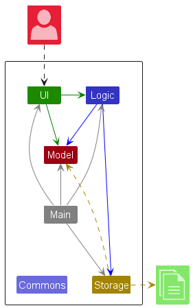
    • An architecture is a higher-level abstraction of the design of a software.
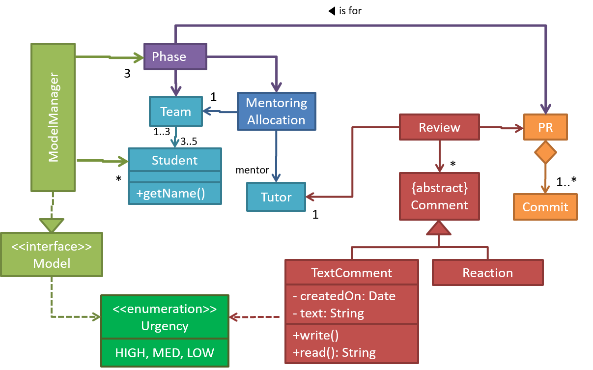
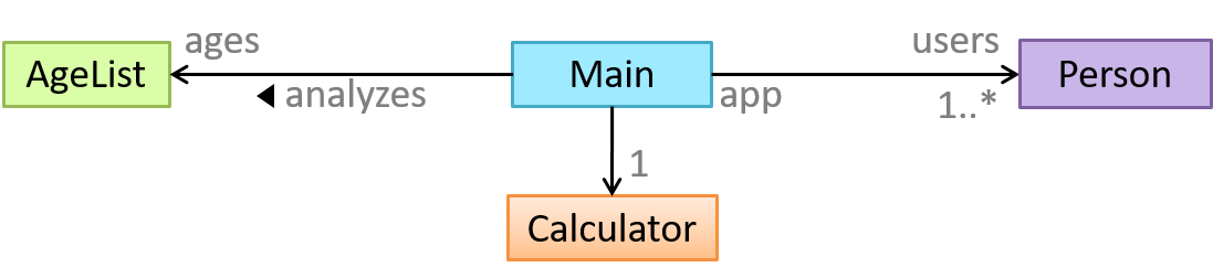
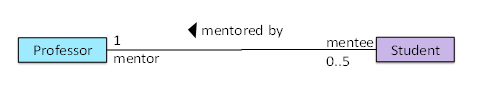
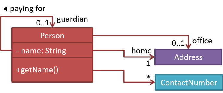
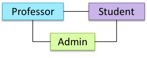
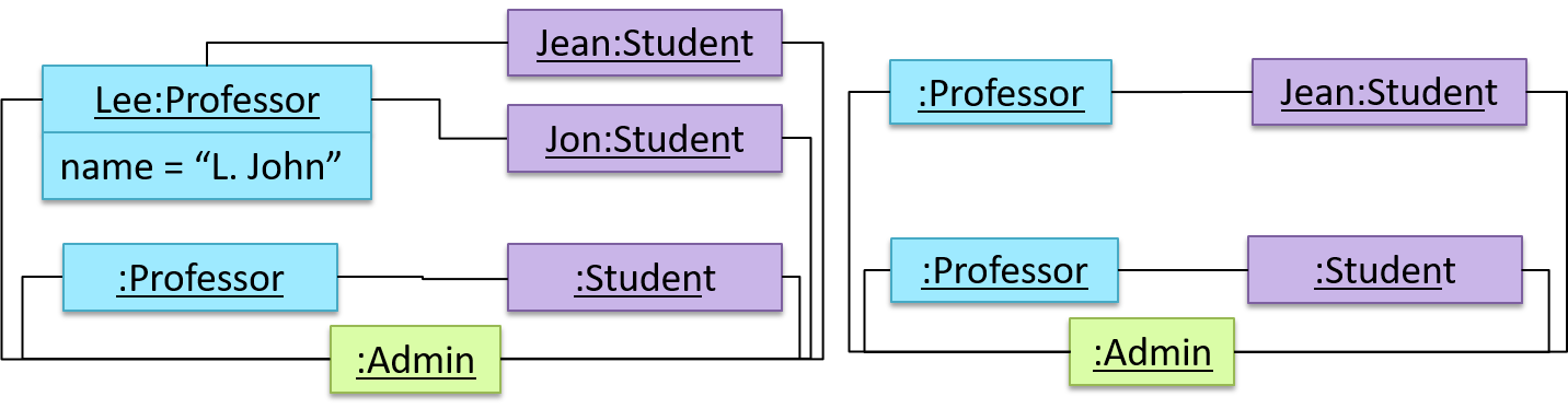
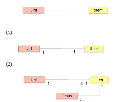
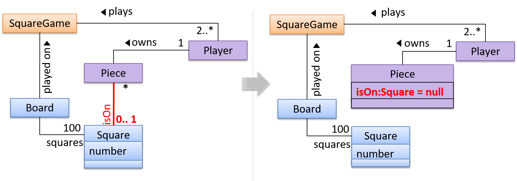
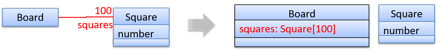
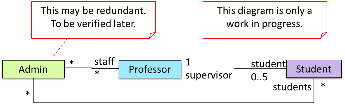
    • Models (e.g., UML models) are abstractions of some aspect of reality.

    A class diagram captures the structure of the software design but not the behavior.

    Multiple models of the same entity may be needed to capture it fully.

    In addition to a class diagram (or even multiple class diagrams), a number of other diagrams may be needed to capture various interesting aspects of the software.

    W8.3c

    Design → Modelling → Introduction → How

    Can explain how models are used

    In software development, models are useful in several ways:

    a) To analyze a complex entity related to software development.

    Some examples of using models for analysis:

    1. Models of the i.e. the environment in which the software is expected to solve a problemproblem domain can be built to aid the understanding of the problem to be solved.
    2. When planning a software solution, models can be created to figure out how the solution is to be built. An architecture diagram is such a model.

    An architecture diagram depicts the high-level design of a software.

    b) To communicate information among stakeholders. Models can be used as a visual aid in discussions and documentations.

    Some examples of using models to communicate:

    1. You can use an architecture diagram to explain the high-level design of the software to developers.
    2. A business analyst can use a use case diagram to explain to the customer the functionality of the system.
    3. A class diagram can be reverse-engineered from code so as to help explain the design of a component to a new developer.

    c) As a blueprint for creating software. Models can be used as instructions for building software.

    Some examples of using models to as blueprints:

    1. A senior developer draws a class diagram to propose a design for an OOP software and passes it to a junior programmer to implement.
    2. A software tool allows users to draw UML models using its interface and the tool automatically generates the code based on the model.
    Model Driven Development extra

    Model-driven development (MDD), also called Model-driven engineering, is an approach to software development that strives to exploit models as blueprints. MDD uses models as primary engineering artifacts when developing software. That is, the system is first created in the form of models. After that, the models are converted to code using code-generation techniques (usually, automated or semi-automated, but can even involve manual translation from model to code). MDD requires the use of a very expressive modeling notation (graphical or otherwise), often specific to a given problem domain. It also requires sophisticated tools to generate code from models and maintain the link between models and the code. One advantage of MDD is that the same model can be used to create software for different platforms and different languages. MDD has a lot of promise, but it is still an emerging technology

    Further reading:

    Choose the correct statements about models.

    • a. Models are abstractions.
    • b. Models can be used for communication.
    • c. Models can be used for analysis of a problem.
    • d. Generating models from code is useless.
    • e. Models can be used as blueprints for generating code.

    (a) (b) (c) (e)

    Explanation: Models generated from code can be used for understanding, analysing, and communicating about the code.

    Explain how models (e.g. UML diagrams) can be used in a class project.

    Can models be useful in evaluating the design quality of a software written by students?

    Guidance for the item(s) below:

    This module covers only two types of diagrams: class/object diagrams (CD/OD) -- which model a structural aspect of an OOP design, and sequence diagrams (SD) -- which model a behavioral aspect. This week, let's learn the basic CD/OD notation.

    We recommend you try the relevant post-lecture quizzes as you read each sections below. In these quizzes, you will be able to see the answers immediately after completing the quiz.

    [W8.4] Class/Object Diagrams: Basics

    W8.4a

    Design → Modelling → Modelling Structure → OO structures

    Can explain structure modelling of OO solutions

    An OO solution is basically a network of objects interacting with each other. Therefore, it is useful to be able to model how the relevant objects are 'networked' together inside a software i.e. how the objects are connected together.

    Given below is an illustration of some objects and how they are connected together. Note: the diagram uses an ad-hoc notation.

    Note that these object structures within the same software can change over time.

    Given below is how the object structure in the previous example could have looked like at a different time.

    However, object structures do not change at random; they change based on a set of rules, as was decided by the designer of that software. Those rules that object structures need to follow can be illustrated as a class structure i.e. a structure that exists among the relevant classes.

    Here is a class structure (drawn using an ad-hoc notation) that matches the object structures given in the previous two examples. For example, note how this class structure does not allow any connection between Genre objects and Author objects, a rule followed by the two object structures above.

    UML Object Diagrams are used to model object structures and UML Class Diagrams are used to model class structures of an OO solution.

    Here is an object diagram for the above example:

    And here is the class diagram for it:

    W8.4b

    Design → Modelling → Modelling Structure → Class diagrams - basic

    Can use basic-level class diagrams

    Contents of the panels given below belong to a different chapter; they have been embedded here for convenience and are collapsed by default to avoid content duplication in the printed version.

    Classes form the basis of class diagrams.

    Associations are the main connections among the classes in a class diagram.

    The most basic class diagram is a bunch of classes with some solid lines among them to represent associations, such as this one.

    An example class diagram showing associations between classes.

    In addition, associations can show additional decorations such as association labels, association roles, multiplicity and navigability to add more information to a class diagram.

    Here is the same class diagram shown earlier but with some additional information included:

    Which association notations are shown in this diagram?

    • a. association labels
    • b. association roles
    • c. association multiplicity
    • d. class names

    (a) (b) (c) (d)

    Explanation: '1’ is a multiplicity, ‘mentored by’ is a label, and ‘mentor’ is a role.

    Explain the associations, navigabilities, and multiplicities in the class diagram below:

    Draw a class diagram for the code below. Show the attributes, methods, associations, navigabilities, and multiplicities in the class diagram below:

    class Box {
    private Item[] parts = new Item[10];
    private Item spareItem;
    private Lid lid; // lid of this box
    private Box outerBox;

    public void open(){
    //...
    }
    }
    class Item {
    public static int totalItems;
    }
    class Lid {
    Box box; // the box for which this is the lid
    }

    Guidance for the item(s) below:

    Object diagrams complements class diagrams and therefore covered together with class diagrams.

    W8.4c

    Design → Modelling → Modelling Structure → Object diagrams

    Can use basic object diagrams

    Object diagrams can be used to complement class diagrams. For example, you can use object diagrams to model different object structures that can result from a design represented by a given class diagram.

    This question is based on the following question from another topic:

    Draw a class diagram for the code below. Show the attributes, methods, associations, navigabilities, and multiplicities in the class diagram below:

    class Box {
    private Item[] parts = new Item[10];
    private Item spareItem;
    private Lid lid; // lid of this box
    private Box outerBox;

    public void open(){
    //...
    }
    }
    class Item {
    public static int totalItems;
    }
    class Lid {
    Box box; // the box for which this is the lid
    }

    Draw an object diagram to match the code. Include objects of all three classes in your object diagram.

    W8.4d

    Tools → UML → Object versus class diagrams

    Can distinguish between class diagrams and object diagrams

    Compared to the notation for a class diagrams, object diagrams differ in the following ways:

    • Shows objects instead of classes:
      • Instance name may be shown
      • There is a : before the class name
      • Instance and class names are underlined
    • Methods are omitted
    • Multiplicities are omitted

    Furthermore, multiple object diagrams can correspond to a single class diagram.

    Both object diagrams are derived from the same class diagram shown earlier. In other words, each of these object diagrams shows ‘an instance of’ the same class diagram.

    Which of these class diagrams match the given object diagram?

    • 1
    • 2

    (1) (2)

    Explanation: Both class diagrams allow one Unit object to be linked to one Item object.

    W8.4e

    Tools → UML → Class Diagrams → Associations as attributes

    Can show an association as an attribute

    An association can be shown as an attribute instead of a line.

    Association multiplicities and the default value too can be shown as part of the attribute using the following notation. Both are optional.

    name: type [multiplicity] = default value

    The diagram below depicts a multi-player Square Game being played on a board comprising of 100 squares. Each of the squares may be occupied with any number of pieces, each belonging to a certain player.

    A Piece may or may not be on a Square. Note how that association can be replaced by an isOn attribute of the Piece class. The isOn attribute can either be null or hold a reference to a Square object, matching the 0..1 multiplicity of the association it replaces. The default value is null.

    The association that a Board has 100 Squares can be shown in either of these two ways:

    Show each association as either an attribute or a line but not both. A line is preferred is it is easier to spot.

    W8.4f

    Tools → UML → Notes

    Can use UML notes

    UML notes can augment UML diagrams with additional information. These notes can be shown connected to a particular element in the diagram or can be shown without a connection. The diagram below shows examples of both.

    Example:

    Guidance for the item(s) below:

    As you are now doing the tP, it is a good time to learn some very basic (almost common sense) techniques that can help in scheduling and tracking your tP.

    [W8.5] Project Mgt: Scheduling and Tracking

    W8.5a

    Project Management → Project Planning → Milestones

    Can explain milestones

    A milestone is the end of a stage which indicates a significant progress. You should take into account dependencies and priorities when deciding on the features to be delivered at a certain milestone.

    Each intermediate product release is a milestone.

    In some projects, it is not practical to have a very detailed plan for the whole project due to the uncertainty and unavailability of required information. In such cases, you can use a high-level plan for the whole project and a detailed plan for the next few milestones.

    Milestones for the Minesweeper project, iteration 1

    Day Milestones
    Day 1 Architecture skeleton completed
    Day 3 ‘new game’ feature implemented
    Day 4 ‘new game’ feature tested

    W8.5b

    Project Management → Project Planning → Buffers

    Can explain buffers

    A buffer is a time set aside to absorb any unforeseen delays. It is very important to include buffers in a software project schedule because effort/time estimations for software development is notoriously hard. However, do not inflate task estimates to create hidden buffers; have explicit buffers instead. Reason: With explicit buffers it is easier to detect incorrect effort estimates which can serve as a feedback to improve future effort estimates.

    W8.5c

    Project Management → Project Planning → Issue trackers

    Can explain issue trackers

    Keeping track of project tasks (who is doing what, which tasks are ongoing, which tasks are done etc.) is an essential part of project management. In small projects it may be possible to track tasks using simple tools as online spreadsheets or general-purpose/light-weight tasks tracking tools such as Trello. Bigger projects need more sophisticated task tracking tools.

    Issue trackers (sometimes called bug trackers) are commonly used to track task assignment and progress. Most online project management software such as GitHub, SourceForge, and BitBucket come with an integrated issue tracker.

    A screenshot from the Jira Issue tracker software (Jira is part of the BitBucket project management tool suite):

    W8.5d

    Project Management → Project Planning → Work breakdown structure

    Can explain work breakdown structures

    A Work Breakdown Structure (WBS) depicts information about tasks and their details in terms of subtasks. When managing projects it is useful to divide the total work into smaller, well-defined units. Relatively complex tasks can be further split into subtasks. In complex projects a WBS can also include prerequisite tasks and effort estimates for each task.

    The high level tasks for a single iteration of a small project could look like the following:

    Task ID Task Estimated Effort Prerequisite Task
    A Analysis 1 man day -
    B Design 2 man day A
    C Implementation 4.5 man day B
    D Testing 1 man day C
    E Planning for next version 1 man day D

    The effort is traditionally measured in man hour/day/month i.e. work that can be done by one person in one hour/day/month. The Task ID is a label for easy reference to a task. Simple labeling is suitable for a small project, while a more informative labeling system can be adopted for bigger projects.

    An example WBS for a project for developing a game.

    Task ID Task Estimated Effort Prerequisite Task
    A High level design 1 man day -
    B Detail design
    1. User Interface
    2. Game Logic
    3. Persistency Support
    2 man day
    • 0.5 man day
    • 1 man day
    • 0.5 man day
    A
    C Implementation
    1. User Interface
    2. Game Logic
    3. Persistency Support
    4.5 man day
    • 1.5 man day
    • 2 man day
    • 1 man day
    • B.1
    • B.2
    • B.3
    D System Testing 1 man day C
    E Planning for next version 1 man day D

    All tasks should be well-defined. In particular, it should be clear as to when the task will be considered done.

    Some examples of ill-defined tasks and their better-defined counterparts:

    Bad Better
    more coding implement component X
    do research on UI testing find a suitable tool for testing the UI

    Which one these project tasks is not well-defined?

    (c)

    Explanation: ‘More testing’ is not well-defined. How much is ‘more’? ‘Test the delete functionality’ is a better-defined task.

    Guidance for the item(s) below:

    GANTT Charts and PERT charts are popular tools in the project management domain but they are rarely useful in small software projects. Hence, they are not included in CS2113 syllabus but it is useful to know at least their names and how they look like.

    W8.5e : OPTIONAL

    Project Management → Project Planning → Gantt charts

    Can explain GANTT charts

    A Gantt chart is a 2-D bar-chart, drawn as time vs tasks (represented by horizontal bars).

    A sample Gantt chart:

    In a Gantt chart, a solid bar represents the main task, which is generally composed of a number of subtasks, shown as grey bars. The diamond shape indicates an important deadline/deliverable/milestone.

    W8.5f : OPTIONAL

    Project Management → Project Planning → PERT charts

    Can explain PERT charts

    PERT (Program Evaluation Review Technique) chart uses a graphical technique to show the order/sequence of tasks. It is based on a simple idea of drawing a directed graph in which:

    • Node or vertex captures the effort estimation of a task, and
    • Arrow depicts the precedence between tasks

    an example PERT chart for a simple software project


    md = man days

    A PERT chart can help determine the following important information:

    • The order of tasks. In the example above, Final Testing cannot begin until all coding of individual subsystems have been completed.
    • Which tasks can be done concurrently. In the example above, the various subsystem designs can start independently once the High level design is completed.
    • The shortest possible completion time. In the example above, there is a path (indicated by the shaded boxes) from start to end that determines the shortest possible completion time.
    • The Critical Path. In the example above, the shortest possible path is also the critical path.

    Critical path is the path in which any delay can directly affect the project duration. It is important to ensure tasks on the critical path are completed on time.

    Guidance for the item(s) below:

    This topic is included in the syllabus just to let you know that teams can be structured in different ways.

    Which of them is closest to the structure of your team?

    W8.5g

    Project Management → Teamwork → Team structures

    Can explain common team structures

    Given below are three commonly used team structures in software development. Irrespective of the team structure, it is a good practice to assign roles and responsibilities to different team members so that someone is clearly in charge of each aspect of the project. In comparison, the ‘everybody is responsible for everything’ approach can result in more chaos and hence slower progress.

    Egoless team

    In this structure, every team member is equal in terms of responsibility and accountability. When any decision is required, consensus must be reached. This team structure is also known as a democratic team structure. This team structure usually finds a good solution to a relatively hard problem as all team members contribute ideas.

    However, the democratic nature of the team structure bears a higher risk of falling apart due to the absence of an authority figure to manage the team and resolve conflicts.

    Chief programmer team

    Frederick Brooks proposed that software engineers learn from the medical surgical team in an operating room. In such a team, there is always a chief surgeon, assisted by experts in other areas. Similarly, in a chief programmer team structure, there is a single authoritative figure, the chief programmer. Major decisions, e.g. system architecture, are made solely by him/her and obeyed by all other team members. The chief programmer directs and coordinates the effort of other team members. When necessary, the chief will be assisted by domain specialists e.g. business specialists, database expert, network technology expert, etc. This allows individual group members to concentrate solely on the areas where they have sound knowledge and expertise.

    The success of such a team structure relies heavily on the chief programmer. Not only must he be a superb technical hand, he also needs good managerial skills. Under a suitably qualified leader, such a team structure is known to produce successful work. .

    Strict hierarchy team

    In the opposite extreme of an egoless team, a strict hierarchy team has a strictly defined organization among the team members, reminiscent of the military or bureaucratic government. Each team member only works on his assigned tasks and reports to a single “boss”.

    In a large, resource-intensive, complex project, this could be a good team structure to reduce communication overhead.

    Which team structure is the most suitable for a school project?

    (a)

    Explanation: Given that students are all peers and beginners, Egoless team structure seems most suitable for a school project. However, given school projects are low-stakes, short-lived, and small, even the other two team structures can be used for them.